
SPEED
EASY NAVIGATION
QUICK RESPONSES
DIRECT SHIPMENTS
GLOBAL SUPPORT
EXCELLENCE
QUALITY SUPPLIERS
PROMPT SERVICE
SATISFACTION IS
#1 PRIORITY
ECONOMICS
LOWEST PRICES
FREE FREIGHT
QUICK DELIVERIES
KNOWLEDGE
FACTORY TRAINED
OTJ EXPERIENCE
ENGINEERING SUPPORT
Gas-Liquid Separator Drainage Best Practices
Separated liquid that cannot leave the vessel becomes re-entrained liquid
Need a separator, float drain trap, or sight gauge selected as a system?
We reply the same business day.

A gas-liquid separator can be properly sized for gas flow and still fail to deliver the expected performance if the drainage system is not designed correctly. The separator may be removing liquid from the gas stream exactly as intended, but if that liquid cannot leave the vessel fast enough, it can accumulate and eventually become re-entrained.
This is one of the most overlooked aspects of gas-liquid separator selection and installation. Drainage should not be an afterthought; it is an essential part of the separation process.
Whether using a float drain trap, a continuous drain, or an automated drain valve, the objective is the same: remove the separated liquid before it interferes with the separator’s performance.
Why Proper Drainage Matters
Centrifugal gas-liquid separators use a combination of centrifugal force, inertia, and gravity to remove entrained liquid droplets from a gas stream. The droplets collect on the separator's internal surfaces, coalesce, and drain toward the bottom of the vessel.
Many centrifugal separator designs incorporate internal geometry to keep the collected liquid from being swept back into the gas stream. If the liquid level rises too high, the gas can pick up the accumulated liquid and carry it downstream. The result is re-entrainment: liquid that was successfully separated from the gas is carried out of the separator because it was not drained away in time.
Float Drain Traps: Automatic Drainage Without Gas Loss
Float drain traps are a common choice for gas-liquid separators because they automatically discharge accumulated liquid without venting the process gas.
Inside the trap, a hollow float rises as liquid enters the body. At a predetermined level, the float opens a valve, allowing system pressure to push the liquid through the drain orifice. As the liquid level falls, the float lowers and the valve closes. A residual volume of liquid remains inside the trap, providing a seal against the escape of process gas.
The most important consideration is drainage capacity at the available differential pressure. The trap must be able to discharge the maximum expected liquid load, accounting for the liquid's specific gravity and any anticipated surges. The drain destination also matters because the pressure against which the trap discharges directly affects its capacity.
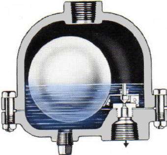
Figure 1. A float drain trap discharges liquid without venting process gas
An orifice that is too small can allow liquid to accumulate in the separator. An unnecessarily large orifice can increase valve cycling and accelerate wear of the valve and seat.
Installation is equally important. Provide the required elevation and piping arrangement so liquid can enter the trap and gas can vent as needed for proper operation. Consider a strainer when rust, pipe scale, or other debris could interfere with the valve mechanism.
When Is a Constant Drain Appropriate?
Depending on the process a continuous drain arrangement may involve a controlled drain valve, an engineered restricted drain, or a continuously operating liquid-removal system.
The mechanical aspects of drainage can be simplified with a continuous drain, and this arrangement may be advantageous when the liquid load is relatively steady.
However, a continuous drain must be designed for the operating pressure, liquid properties, and expected flow rate. An unrestricted opening from a pressurized gas system can discharge process gas along with the liquid, wasting gas and creating an operating hazard. This mostly limits continuous drainage to steam systems (where some leakage might be acceptable) and to exhaust heads (where the gas is vented anyway).
A restriction alone is not a substitute for proper engineering. The opening must be sized for the required liquid removal rate while accounting for the pressure differential and the possibility of gas flashing or passing through the drain.
Using High/Low Ports for Liquid Level Switches
Certain gas-liquid separator designs include built-in liquid hold-up capacity and high/low level ports. These ports can be used for visual level indication or liquid-level instrumentation, providing an opportunity to monitor liquid accumulation and automate drainage. A float drain trap may not be the best choice when drainage needs to be coordinated with other process equipment or operators need remote indication of liquid accumulation.
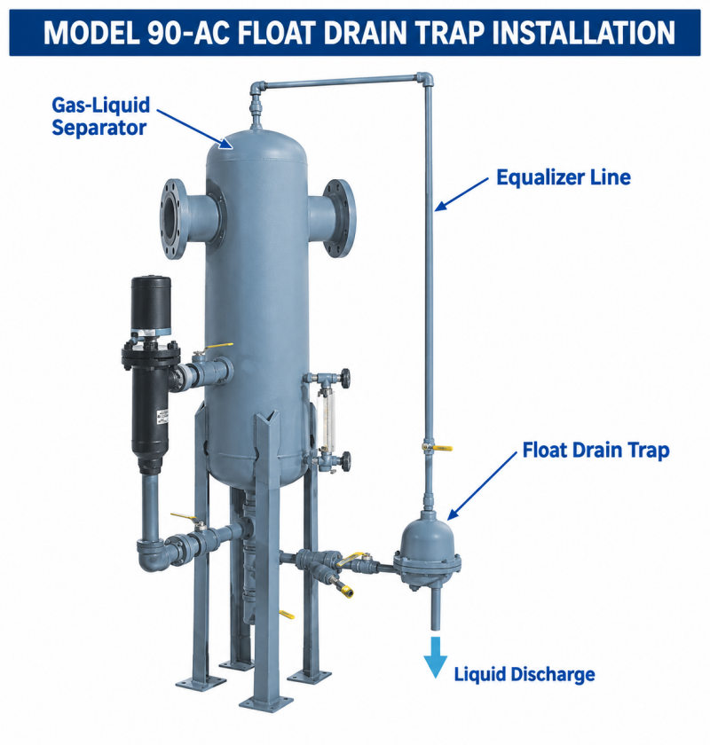
Figure 2. High/low ports for sight gauges or liquid level switches
A liquid level switch can be installed to signal a control system when the liquid reaches a predetermined level. The control system can then open a drain valve or operate a pump to remove the collected liquid. A separate high-level alarm can provide an additional warning if the level continues to rise.
The separator must have enough liquid hold-up capacity between the normal operating level and the point where re-entrainment becomes likely. The switch, control logic, and drain valve must also respond quickly enough to prevent the liquid from reaching a critical level.
A Simple Way to Verify Drainage
A sight gauge provides something that many automatic drainage systems lack: a direct visual indication of the liquid level inside the separator.
Many separator designs offer sight-gauge ports that allow an operator to observe whether liquid is accumulating, whether the drain is keeping pace with the incoming load, and whether the liquid level returns to its normal range after a surge.
This is valuable during commissioning, troubleshooting, and routine operating inspections. A separator may appear to be working normally while its drain is partially obstructed or undersized.
Common Drainage Failures That Cause Re-Entrainment
When liquid carryover occurs downstream of a separator, check the drainage system and operating conditions. Common causes include:
- Undersized drain trap: The trap cannot discharge the maximum liquid load, particularly during surges or liquid slugs.
- Blocked or restricted drain: Rust, scale, debris, viscous fluids, or deposits restrict drainage through the trap, valve or drain piping.
- Incorrect installation: Poor elevation, unsuitable piping, or an arrangement that prevents proper trap filling or gas venting interferes with drainage.
- Worn valve or seat: A float trap that no longer seals correctly may leak process gas; internal damage or sticking can also impair normal operation.
- Inadequate control response: A level switch, control valve, or pump may not respond quickly enough to keep the liquid below the critical level.
- Insufficient liquid hold-up capacity: Some separator designs provide a dedicated volume to temporarily hold separated liquid. If the liquid level rises above the internal vortex-containment plate, liquid can be swept back into the gas stream. Where drainage is controlled by a level switch, valve, or pump rather than a float drain trap, confirm that the separator provides sufficient hold-up volume and that the control system can respond before the liquid reaches the critical level.
- Unsuitable drain technology: Heavy solids, sludge, gummy fluids, or other difficult service conditions may require a different drainage design rather than a conventional float trap.
Freezing, corrosion, and inadequate maintenance can also compromise drainage reliability. Periodic inspection should confirm that the drain operates as intended and that liquid is not accumulating beyond the normal operating range.
Make Drainage Part of the Original Design
The best time to address drainage is when the separator is being selected—not after liquid carryover becomes a problem.
Determine the maximum expected liquid load, identify whether slugs or surges are possible, and establish the pressure differential available for drainage. Then select the appropriate drain technology, size the trap or valve for the actual service, and provide enough liquid hold-up capacity to accommodate the operating conditions.
Where practical, include a sight gauge or suitable level instrumentation so drainage performance can be verified rather than assumed.
A properly selected gas-liquid separator removes entrained liquid from the gas stream. A properly designed drainage system ensures that the separated liquid stays separated.
Related pages
Need help selecting a separator, float drain trap, or sight gauge for your application?
We reply the same business day.