Steam Traps vs. Steam Separators
Efficient removal of condensate for higher quality steam
Steam traps and steam separators are both
used to improve quality of steam by removing liquid condensate but they
are applied in different sections of piping. Whereas steam traps are
always used in conjunction with stream separators, they are also used in
other sections of piping where condensate accumulates. This article
explains how mechanical steam traps and steam separators function,
individually and together, to improve steam quality.
Steam Traps
A steam trap is designed to separate and drain
condensate, air and other incondensable gases (gases dissolved in water)
from a steam system to increase heating efficiency and reduce
maintenance costs associated with corrosion, leakage and damage to
pipeline components. There are several steam trap designs, some operate
based upon fluid temperature, mechanical traps rely on fluid density and
others react to changes in fluid dynamics such as flash steam. In all
cases steam traps are installed in the lowest sections of piping because
that is where condensate collects.
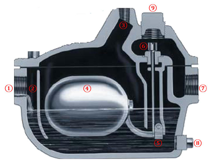
Below is an example of a
mechanical steam trap. Condensate enters from the
① side inlet port. The
② internal baffle at the point of
entry helps separate entrained gas which is vented through the
③ uppermost threaded port. The vent
line can be plumbed back to the system or sent to atmosphere as dictated
by the application.
 Within
the steam trap is an ④
oblong float made of 18-8 stainless steel. Its buoyancy is pre-set
due to sand contained within the float. Attached to the float is a
⑤ fulcrum and lever. As the chamber of the
steam trap fills with condensate, the air and other gasses are displaced
via the vent until the float rises sufficiently to rise the
⑥ valve plunger
(attached to the lever) from its valve orifice or "seat". To reiterate,
the upwards (rising) motion of the float corresponds to a downward
movement of the valve plunger, unseating it from the valve orifice,
allowing the condensate to ⑦
drain from the trap. When drained sufficiently, the float is
lowered and the plunger is re-seated against its orifice.
The
⑧ lower drain plug
illustrated above is for draining the trap prior to service as well
periodic blow-down to remove sediment which may accumulate. It is
important to note that the liquid within the trap is a barrier
preventing steam (or other gas) loss via the drain port. If installed
where freezing is a concern, an optional heating element can be
installed through this port which keeps the retained condensate from
freezing and damaging the steam trap.
The
⑨ large plug over the valve orifice enables
periodic valve seat and plunger replacement as these components will
eventually wear to the point where they no longer seal well.
The
orifice diameter and system pressure dictate the condensate removal
rate. The steam trap illustrated on this page has a 7/32" orifice and
can drain condensate at a rate of 2500 lbs/hr at 100 PSI, equivalent to
about 5 GPM. As a safety factor, the trap you select should have a
capacity of 10-40% greater than your expected liquid load.
Thermomechanical and dynamic steam traps accomplish the same task but
are actuated by either temperature or dynamics such as flash steam; some
applications benefit from specific types of steam drain traps (a subject
for a future article).
Mechanical steam traps are often referred
to more generically as "float drain traps" because they are also used in
non-steam systems to drain liquid condensate.
Steam
Separator Design
Centrifugal steam separators also remove
condensate from pipelines, with the primary difference between steam
separators and traps being separators remove entrained droplets and
traps remove coalesced condensate from steam pipelines. Thus, steam
separators and steam traps are often used together to improve steam
quality as well as to protect downstream components from entrained
droplets and particles larger than 10 microns. Steam separators create
coalescence, increasing the volume of liquid that can be drained via the
steam trap.
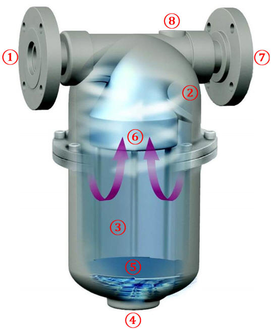
 ①
Steam enters the separators inlet and an internal vortex is
created due to the internal suction nozzle protruding into the center of
the vortex and the ②
internal baffles angled towards the cylindrical body of the separator.
Entrained droplets larger than 10 microns either impinge onto the
internal surfaces or are propelled by centrifugal force within the
③ main body to the ribbed inner
walls of the separator. The impinged droplets coalesce and drain to the
④ bottom of the vessel.
The ⑤ vortex containment
plate (VCP) prevents condensate from becoming re-entrained or
"sucked-up" by the internal vortex. The volume between the VCP and drain
port is the liquid hold-up capacity of the separator; its the maximum
volume of condensate that can be stored prior to re-entrainment.
Only droplets smaller than 10 microns remain
within the center of the vortex, pass through the
⑥ suction nozzle and
⑦ exit the separator.
Centrifugal separators are 99% efficient for removing entrained droplets
and particles larger than 10 microns and due to the centrifugal force
within, they are considered self-cleaning.
This no-maintenance aspect differentiates
centrifugal separators from vane, baffle and demisting pad separators
which require periodic cleaning, have high higher differential pressure
drops across the separator body and are limited to a specific turn down
ratio. A centrifugal separator has an infinite turndown ratio, meaning
it retains its droplet removal efficiency of 99% no matter how much the
flow is reduced; this is not the case with vane and baffle styles which
rely on turbulence or torturous pathways for droplet separation. This
aspect is most critical for applications involving lower flow rates
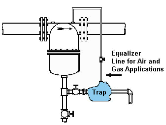
associated with start-up/shut down or upset conditions. The ⑧
equalizing or vent port may be used for side-entry style drain
traps to facilitate drainage of condensate.
 Working
Together
Steam traps are used to remove the condensate from
the separator body. The plumbing between the separator drain port and
inlet of the trap depends upon the specific trap model but will often
include a sediment strainer to protect the trap.
Just as steam separators and steam traps work together to optimize a steam system, we work with YOU to properly size separators and traps for your specific application. Call us at 908.362.9981 or use our inquiry form for immediate assistance with your application!


