Centrifugal Separator Designs for Non-Newtonian and Slurry-like Entrained Liquids
Got Hot, Dirty Gas?
 The
first cyclonic gas-liquid separator was invented by Ralph W. Busse in
the 1930s. Busse was a mechanical engineer and inventor who developed
the cyclonic separator while working for the Universal Oil Products
(UOP) company. The device was originally designed to remove entrained
liquid droplets from natural gas streams, which were becoming
increasingly important as a fuel source at the time. Busse's invention
revolutionized the natural gas industry and is still widely used today
in a variety of gas processing applications.
The centrifugal gas-liquid separators described in this article do not use rotating internal components, rather they rely on the geometry of the separator itself to separate the gas and liquid phases. These separators are sometimes referred to as "cyclonic" and “vortex” separators, and they work by taking advantage of the difference in density between the gas and liquid phases.
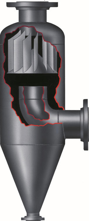
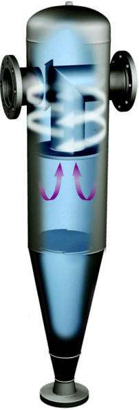
The gas-liquid mixture enters the separator through an inlet and is directed into a cylindrical or conical chamber. Depending upon the separator model the mixture enters the separator vessel and either is deflected downwards or passes through a cyclo-impeller oriented perpendicular to the direction of the incoming fluid stream. The Wright-Austin Company referred to its cyclo-impeller as a cempeller, a stationary blade-like structure affixed to the inner circumference of the gas-liquid separator vessel. The purpose of the cyclo-impeller is to create a rotating motion in the fluid as it enters the separator. The separator’s design in which the incoming gaseous mixture is deflected downward generates centrifugal rotary motion by the conical shape of the vessel with a downwards flow path due to the location of the exit nozzle orifice protruding below the inlet nozzle centerline of the vessel.
The centrifugal rotary motion causes the entrained droplets and particles
to rotate away from the center of rotation, thus to the outer walls of the
vessel. The larger size droplets with a heavier mass are forced to the
outer wall first and the finer (lower mass) droplets take longer to impinge onto
that surface. A degree of angular momentum assists with separation
although it is not the primary separation mechanism.
Role of Velocity and Centrifugal Force
The centrifugal rotation of the gaseous flow establishes a centrifugal “force field” that separates the gas and liquid phases, with the heavier liquid being forced towards the outer wall of the separator, where it coalesces and gravity drains to the bottom of the vessel for drainage. This type of centrifugal gas-liquid separator is also particularly useful in applications where solid particles or other contaminants are present in the fluid stream.
The blade shape and orientation of the cyclo-impeller is carefully engineered to create the desired flow pattern in the fluid stream while the other geometry within the separator is designed to optimize the separation of the gas and liquid phases. This typically involves using a conical or tapered chamber, which helps to increase the velocity of the gas-liquid mixture as it enters the separator, creating a stronger vortex and enhancing the separation effect.
Role of Pressure Drop
Pressure drop is the decrease in pressure that occurs as the gas-liquid mixture passes through the separator. In cyclonic gas-liquid separators, pressure drop plays a critical role in the creation of the vortex that separates the gas and liquid phases. The design of the separator is optimized to create a pressure drop that is sufficient to generate the necessary centrifugal force to separate the gas and liquid phases, while still minimizing the overall pressure drop of the system. Higher pressure drops characteristic of vane separators and other designs more reliant upon tortuous pathways for separation, can increase the separation efficiency, but they also increase energy consumption, reducing overall system efficiency. Such designs tend to be physically larger and more expensive than a cyclonic gas-liquid separator design.

 Role
of Residence Time
Residence time, which is related to the pressure drop, is another key aspect of efficient gas-liquid separation. Increased residence time is why cyclonic gas-liquid separators have an infinite turn-down range (maintain their efficiency at lower flow rates).
At first one might think that the reduced velocity due to the lower flow rate reduces the centrifugal force and thus efficiency. However, cyclonic gas-liquid separators maintain their efficiency at lower flow rates due to increased residence time within the separation vessel, so efficiency is maintained or even increased for low flow rate conditions. Since gravity is a constant force, it is equally effective at separating droplets at higher and lower velocities. However, the centrifugal force becomes more effective at separating droplets at lower velocities because the droplets have a greater chance to move towards the outer wall of the vessel due to the prolonged residence time. This characteristic is advantageous for systems where the flow rate “ramps-up” to full capacity during start-up and “ramps down” during shut down; it is also advantageous where upset conditions may sometimes affect the flow rate.
A vortex containment plate (VCP), also known as a "vortex breaker", is used to control the flow pattern of the separated liquid/particles and prevent them from re-entering the gas outlet stream. The VCP is typically affixed to the inner circumference of the separator vessel towards the lower end, near the drain port.
As the gas-liquid mixture enters the separator vessel and is subjected to centrifugal forces, the heavier liquid phase is forced towards the outer wall of the vessel, where it collects and flows downwards towards the drain port. In some designs, the liquid may tend to form a swirling vortex as it exits the vessel, which can entrain gas and cause it to re-enter the gas outlet stream.
Thus the VCP also helps disrupt this swirling motion and prevent gas entrainment. It works by creating a barrier that forces the liquid to flow around it, rather than forming its own vortex. This helps to maintain a clear separation between the gas and liquid phases, ensuring that the gas outlet stream remains free of liquid droplets and particles.
Overall, the design of cyclonic gas-liquid separators must balance the trade-offs between pressure drop and angular momentum to optimize the separation efficiency and overall performance of the separator. The goal is to create a design that generates sufficient centrifugal force to effectively separate the gas and liquid phases, while minimizing energy consumption and pressure drop.
Non-Newtonian Fluids
Cyclonic gas-liquid separators are used for the separation of non-Newtonian liquids in a variety of industrial applications. Non-Newtonian liquids are complex liquids that exhibit different flow behaviors under different conditions. Examples of non-Newtonian liquids include emulsions, suspensions, and slurries.
One example of an application where cyclonic gas-liquid separators are used to separate non-Newtonian liquids is in the oil and gas industry. During the production of crude oil, the produced liquids often contain significant amounts of non-Newtonian materials, such as sand, drilling mud, and other debris. Cyclonic gas-liquid separators can be used to remove these materials from the produced liquids, allowing for more efficient processing and transportation.
Another example of an application for a cyclonic gas-liquid separator is found in the cement manufacturing industry. During the production of cement, raw materials are ground into a fine powder and mixed with water to form a slurry. This slurry is then transported through pipelines using air or an industrial gas, such as nitrogen, to be dried and further processed.
During the transportation process some of the slurry can become entrained in the air or gas stream. This slurry can cause blockages in the pipelines and other equipment, leading to costly downtime and maintenance.
Cyclonic air-liquid separators are used to separate the slurry from the air or gas stream before it enters the pipelines. The slurry-laden air or gas stream is fed into the separator, where it is rapidly spun around in a vortex. The centrifugal force generated by the spinning motion causes the heavier slurry particles to move towards the outer wall of the separator, while the lighter air or gas is drawn towards the center. The separated slurry can then be collected and further processed or disposed of, while the air or gas can be recycled back into the system.Cyclonic air-liquid separators are particularly useful in this application because they can effectively separate slurry-like liquids from air or industrial gases, even when the slurry is very dense and contains large particles. This helps to prevent blockages in the pipelines and other equipment, ensuring efficient and continuous operation of the cement production process.
 Design
Modification for Drainage of Slurries
The drainage area of cyclonic gas-liquid separators which are specifically designed to handle slurries and high percentages of solids are modified to ensure drainage without clogging. The drainage port is both oversized and significantly tapered to facilitate drainage of thick, slow moving material. We can significantly oversize the drainage section to handle almost any drainage and clean-out requirement.
CaF2 Waste Slurry
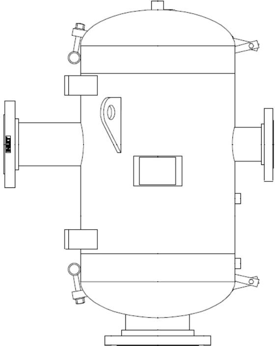
Calcium Fluoride crystals are utilized during semiconductor manufacturing for microlithography as a flux to protect areas of a silicon wafer from etching. The silicon wafers are eventually washed and dried, resulting in CaF2 based industrial waste sludge, some of which becomes entrained within the air system during the manufacturing process. The CaF2 slurry can be reclaimed and recycled as fine aggregate material for a wide variety of construction applications, converting a toxic waste material into a saleable byproduct of semi-conductor manufacturing. Our standard receiver style gas/liquid separators are used to recover the CaF2 slurry due to their ability to handle a high percentage of entrained liquid and particles within a compact design. To ensure proper drainage, ease of inspection and periodic clean-outs, the drain is modified to be oversized and both the top and bottom portions of the vessel can be accessed with quick-opening, hinged covers. This is another example of a standard product modified to handle specific fluid characteristics and manufacturing processes.
Let us put our considerable experience to work for you! You can easily call and speak to a factory trained sales engineer or use the online live chat function to receive immediate feedback and answers to your questions!


