Condensate Drain Traps
Liquid float drain traps
Call us at 908.362.9981 to speak with a sales engineer


Automatic
float style condensate traps provide a reliable method of
automatically draining liquid from a pipe system without loss of
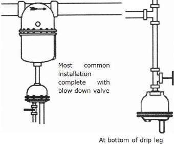
any process gas. Float drain traps are typically installed
at low points in the plumbing system where liquid accumulates
from storage tanks, gas/liquid separators and at the bottom of
vertical piping.
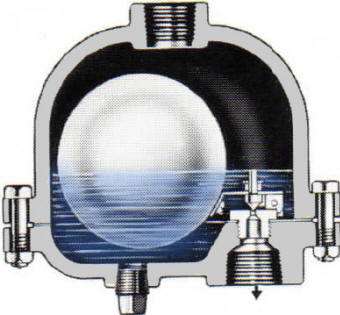
How Float Drain Traps Work
Liquid flows into the drain trap from
above and fills the trap until the hollow stainless steel ball
floats sufficiently high enough to open the valve attached to
it. The system pressure acts upon the liquid and it passes through
the valve to drain until the level within the trap drops
sufficiently, causing the float to drop low enough to seal the
drain orifice closed. A
detailed article illustrating this style of drain trap, installation
guidelines, maintenance and troubleshooting can be viewed online
"Float drain traps, how they work, applications and maintenance"
(PDF).
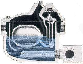
Inside of a typical float style drain trap
| Lower half of model 90/95-AC trap with float attached. | Float extended to reveal valve orifice | Close-up view of valve plunger and seat |
|
|
|
|
At all times there is a barrier of
liquid within the trap, thus only the liquid drains from the
trap and the steam, compressed air or other inert gas stays
within the piping system. The lower plug is used for
occasional blow down if particulate such as pipe scale are
introduced into the trap. Installing a Y strainer to
protect the trap from excessive scale found in older systems is
a good idea. All of the serviceable components are
attached to the drain trap cover for easy inspection and
maintenance.

When installed in locations susceptible to
freezing, we offer models that have an extra port in which a 50 watt
heater can be installed; this keeps the trap reservoir from freezing.
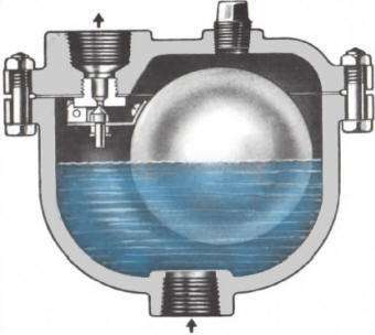
 Air Vent Trap
Some of our float drain traps can be used as a vent trap. Whereas float drain traps are used in low sections of piping to drain-out accumulated liquid, you can invert some drain traps and install within high sections of piping to eliminate accumulated air/steam/gas. The process is simply reverse; gravity ensures the discharge vavle is open when not filled with liquid, thus allowing trapped gas to vent. Once liquid sufficiently floats the ball, the valve orifice is closed. These are commonly installed on high capacity water pump systems to assist with venting air entrapped within the pump head and piping during start-up priming.
Capacity Chart
The following chart provides the estimated flow rates for a given orifice size at various pressures. It is accepted practice to incorporate a 3:1 safety factor when selecting your drain orifice size; thus if your expected liquid load is 50 lbs/hr, use an orifice which can handle up to 150 lbs/hr. If your expected liquid load is > than the flow rates below, or if your differential pressures are higher, contact us for information on additional designs.
You can calculate the approximate flow rate for other pressures using the formula provided where:
Q1 and P1 are the known flow rate and pressure
Q2 is the resulting flow rate for the desired pressure P2

DOCUMENTATION
-
Outline Drawing: Cast Iron model 90-AC
-
(note: side inlet version was discontinued, see alternate: Type S trap for a side inlet version equivalent to the 90-AC)
-
-
Installation, operation and maintenance manual for type 90 & 95 flat drain traps


