Comparison of Centrifugal and Vane Style Gas Liquid Separators

Centrifugal separators are the most common design used to remove entrained droplets and particles from gaseous processes although there are applications which benefit from a vane design. Following is a comparison of both designs to assist with selecting the most appropriate version for your application.
 Centrifugal and Vane Designs
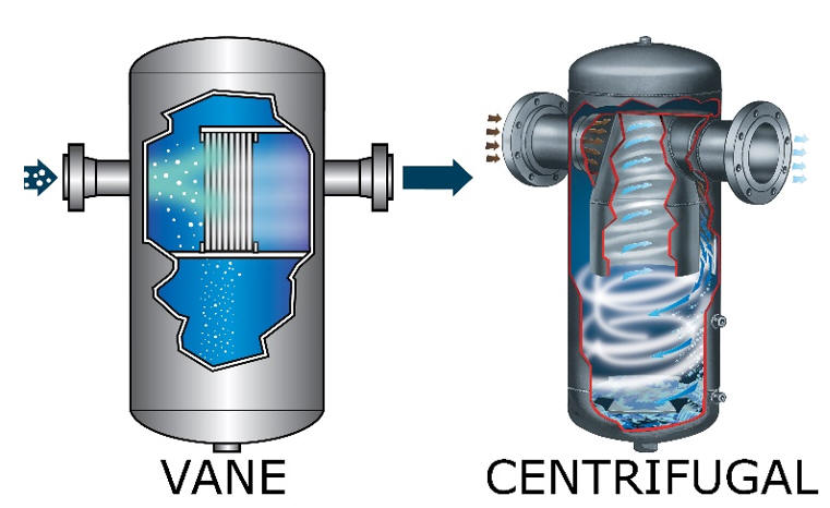
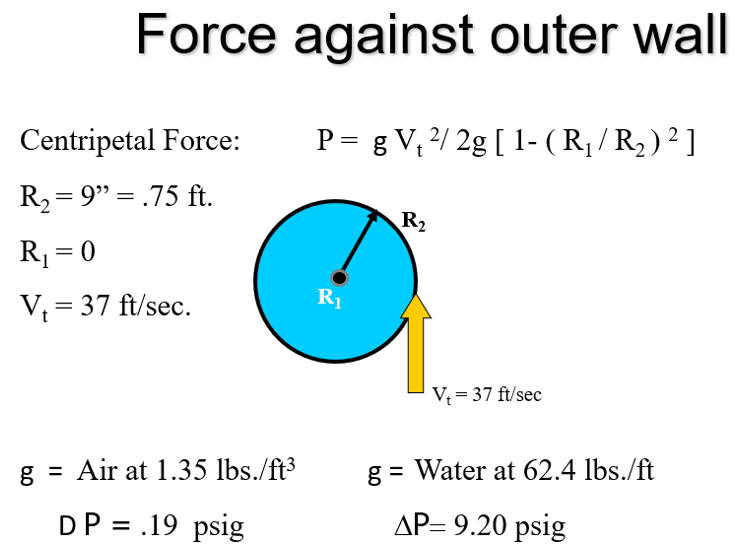
A centrifugal gas/liquid separator relies on Newton's first law (law of inertia) and conservation of angular momentum; centrifugal force propels entrained droplets and particles downwards and away from the center of the cylindrically shaped vessel where they coalesce and drain to a common sump. The centripetal force is proportional to the mass of the droplet/particle and the ratio of tangential velocity within the vessel. Simply put, the density contrast between the process gas and droplet/particle is significant enough that performance is maintained even at low flow conditions. When properly sized they are 99% efficient for removing entrained droplets and particles larger than 10 microns. The gas discharges through an exit nozzle which is extended internally within the vessel near the center of the vapor vortex. The simplified geometry renders this a self-cleaning, maintenance-free design for the life of the vessel (often measured in decades).
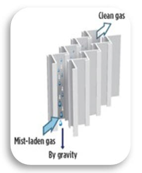
A vane separator also relies on Newton's first law, although instead of centrifugal force the droplets and particles impinge upon surfaces of baffles forming a torturous exit path. Most vane designs result in slightly higher droplet removal efficiency, 100% of entrained droplets and particles > 8 microns are removed. Some manufacturers state their efficiency as fine as 100% for droplets and particles > 5 microns with the increased efficiency attributed to the complexity of the internal vane design.
 Vane
Design
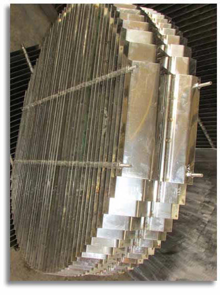
The most basic vane design consists of baffles
designed to maximize the open area (minimize flow resistance/pressure
drop) while creating a complex pathway which droplets impinge upon. The
resulting liquid film and coalescence form into larger droplets which
drain to a common point and are routed to the separator sump. The
complexity of the vane includes pathways to isolate the separated liquid
from re-entrainment into the process gas.
 Thus,
a vane separator is a type of coalescing separator with the additional
internal geometry increasing the efficiency of droplet removal and
enabling finer droplets to be removed. Our article “Coalescer Gas/Liquid
Separator Designs” illustrates multistage coalescer designs, employing a
centrifugal separator section with a coarse (demisting pad) or fine
(coalescing filter cartridge) stage for removal of droplets as fine as
0.3 microns.
Applications for Coalescer and Vane Separators
The complexity of the internal geometry within vane separators results in higher differential pressure unless the physical vessel size is increased to compensate accordingly. Even when the difference in differential pressure is not significant, both coalescer and vane separators are designed to be opened and for the internal vanes, cartridges and pads to be removed for cleaning or replacement. This requires coalescer and vane separators to have a flanged body or removable dished head to enable access to the internals without disconnecting the vessel from the pipeline. These characteristics relegate coalescer and vane separators to 2” and larger size pipelines; they can be fabricated with smaller connections however the body size is commensurate with the diameter and length generally required for installation into 2” and larger size pipelines.
Generally speaking, vane and coalescing separators perform best when applied to applications having liquid and particles which are not waxy, sticky or viscous. Any liquid and particle combination that might result in plating or build-up will result in increased differential pressure, reduced efficiency and necessitate cleaning or replacement of the internal element(s).
Since vane style separators typically cost
50% to 80% more than centrifugal separators due to their larger physical
size and internal complexity, the application needs to be sensitive
enough to droplets of 6-10 microns in size to justify the additional initial
expense and periodic maintenance requirements.
The most common
application for vane separators is within steam systems prior to
expensive turbo compressors whose fan blades are especially sensitive to
damage from droplet impingement. In such applications fouling of the
vane assembly is not an issue and the increased cost for the vane design
is easily justified given the costs involved for repair of turbine
systems.
Centrifugal separators are a better choice
when the liquid and particle load result in gummy, slimy and sludge-like
deposits; such materials would tend to foul a vane assembly. Centrifugal
separators are also more compact and a less expensive choice for any
application where an efficiency of 99% for removal of droplets greater
than 10 microns is acceptable. Centrifugal separators are used throughout
the petrochemical, power generation and various manufacturing industries
to protect downstream equipment and processes from excessive droplets
and particles; in some cases the separated material is the product and
the gasses are a byproduct of the manufacturing process.
Centrifugal separators are also available in
cast iron material for pipelines up to 4” in size, vane separators
cannot be cast, only fabricated. Cast iron centrifugal separators are
inexpensive and readily available compared to fabrication lead times of
4+ weeks required for vane separators. Compressed air systems often have
cast iron centrifugal separators for removing both water and trace
lubricants ahead of desiccant filters or to protect sensitive
instrumentation or products from entrained liquid.
Typical Centrifugal Separator Applications
-
Steam Service
-
Compressed Air & Gas
-
Natural Gas Applications
-
Geothermal Steam Collection
-
Volatile Organic Vapor Collection
-
Landfill & Waste Gas Collection
-
Food Processing Plants Oil Mist
Comparison of Vane and Centrifugal Separators
The efficiency of vane separators is dependent upon an acceptable range of velocity through the internal vane baffles; when the velocity is above or below the optimal range, efficiency suffers. The rate of liquid separation is also limited for vane separators – too much liquid and carry-over will occur.
Like vane
separators, the efficiency of centrifugal separators suffers from
excessive velocity, but unlike vane separators they have an infinite
turndown ratio, thus during low flow conditions related to system
start-up and shut down they maintain their efficiency. The vessel design
of both vane and centrifugal separators can be modified to mitigate
slugs of liquid due to upset conditions however the orientation of the
inlet and outlet nozzles for vane separators is limited in comparison to
centrifugal separators and therefore vane style separators are usually
larger for a given application when the liquid load is high.


