AIR SEPARATOR TANKS
Air Separators remove entrained air from closed loop heating systems
Call us at 908.362.9981 to speak with a sales engineer
![]() Degassing separator
specifications
Degassing separator
specifications

Air
separator tanks are used to remove entrained air within liquid systems,
applicable to both open and closed loop heating systems. It is important to remove
entrapped air because it reduces the heat system efficiency and precise
control of temperature. Systems using air separators often require less
chemicals for pH and corrosion control because dissolved oxygen, carbon
dioxide and other non-condensable gasses are removed from the condensate on
its way to the feed tank.
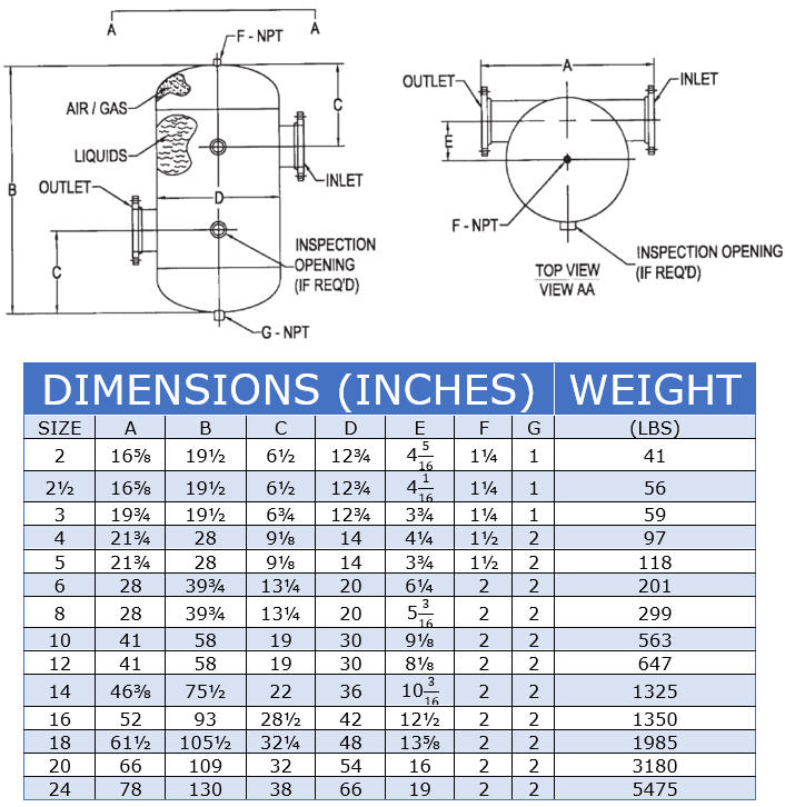
To remove the entrained air, the
condensate enters the separation tank tangentially to the vessel body,
creating a centrifugal vortex downwards towards the lower tangentially
mounted outlet nozzle (the tangential nozzle orientation accomplishes air
separation with the minimal tank body size possible). The resulting
low velocity centrifugal force propels the heavier "air free"
condensate towards the outer edges, releasing the entrained air into the center of the swirling vortex
where it can rise upwards through the vessel vent port and
float style air vent.
Sediment collects within the lower dished head section and can be
periodically blown-down from the system as required.
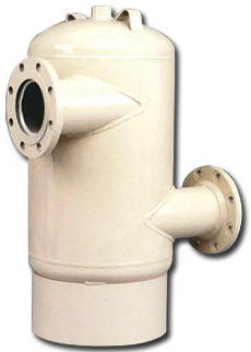 Our standard air separator
tanks are constructed of carbon steel and both designed and manufactured
in accordance with the latest edition of ASME Code Section VIII Div. I,
including code stamp. Tanks 3" and larger are offered with 150# ANSI
flanged nozzles, although as a custom fabricated vessel we can
accommodate whatever type of connection is most compatible with your
design. We have constructed air separation tanks from stainless steel
and for working pressures up to 3,000 PSIG.
How to Size
Air Separator Vessels
Each
air separator vessel size has an associated maximum capacity rating and
a Cv rating (used to calculate pressure drop across the vessel).
Step 1: Select an air separator vessel size having a
maximum capacity larger than the maximum flow rate for your application.
Since these are custom fabricated pressure vessels, we can reduce the
inlet/outlet connection size to match your pipeline, so base sizing on
the smallest vessel size which satisfies your intended flow rate.
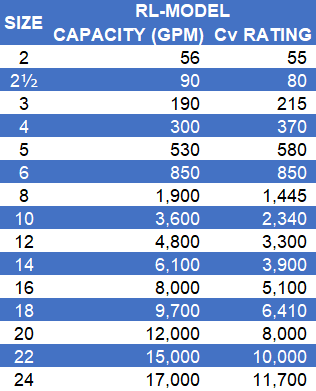
Step 2: Divide your maximum flow rate by the
maximum capacity to obtain the percentage of the total capacity used.
For example, lets say that your application uses 350 GPM and you are
looking to maximize air separation, choosing an 8" size vessel (having a
maximum capacity of 1,900 GPM; this equates to using about 18.42% of the
total capacity available.
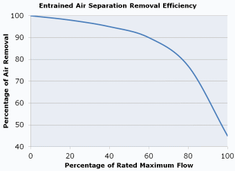
Step 3: Draw a
vertical line from the capacity used (18.42%) and where it intersects with the
efficiency curve is the approximate air removal efficiency; continuing
with our example, an 8" size air separator vessel would eliminate
approximately 98.5% of entrained air with each pass through the unit.
In a closed loop system, such as a boiler system, it might require several passes to remove most
of the air from your system and thereafter only air attributed to make-up
water will need to be removed.
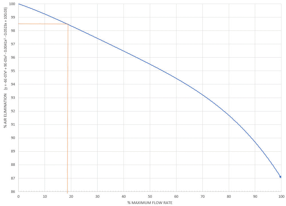
You can also work the formulas backwards, determine the desired efficiency, find the corresponding % of maximum capacity value and divide your flow rate by that percentage: (350 GPM/0.1842) = 1,900 GPM, so you would be looking for an air separator size that has a maximum capacity of at least 1,900 GPM. Once again, if the "vessel size" is larger than your inlet/outlet piping, we can simply reduce the connection sizes to match your piping.
The estimated differential pressure is the [flow rate/Cv]^2 = [350/1445]^2 = 0.058 PSI or 0.14 FT.
