Knockout Drums vs. Centrifugal Gas-Liquid Separators: A Comparison
Call us at 908.362.9981 to speak with a sales engineer
How do knockout drums stack up against centrifugal gas-liquid separators? This article breaks down their designs, efficiencies, and uses. Knockout drums, like those in flare systems, remove bulk liquids, while centrifugal separators offer precision and lower maintenance. Read on to find the best fit for your needs.
The terms knockout drum and gas-liquid separator are often used interchangeably although a knock-out drum is really a type of gas-liquid separator application. This article describes the typical knock-out drum application and how gas-liquid separators can be applied to maximize performance.
Gas-liquid separators are used in two phase processes to separate entrained liquid and droplets from a gaseous flow. Our separators are designed based upon using centrifugal force while other designs use schoepentoeters to reduce momentum and coalesce liquids; both designs rely on gravity to drain separated liquid from the vessels. These two styles of separators are compared in our article “Comparison of Centrifugal and Vane Style Gas/Liquid Separators”.
| Feature | Knockout Drum | Centrifugal Separator (R-Series) |
|---|---|---|
| Liquid Removal | Bulk | Fine droplets |
| Maintenance | Higher | Lower |
| Best For | Flare systems | Pipelines, compressors |
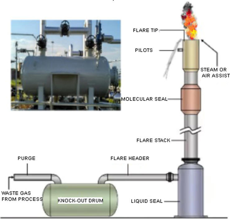
A knock-out drum accomplishes separation by reduction in velocity and typically it is used prior to gas combustion devices such as flare burners although can be used for recovering entrained product. The term knockout drum is most often associated with natural gas and refinery applications and is a simply designed vessel without internal structure. Too much liquid can reduce combustion efficiency or result in a significant safety hazard such as a burning rain-like spray during upset conditions and a knock-out drum will cause much of the entrained droplets to fall out prior to being drained or pumped from the vessel.
In its simplest form a knockout drum is a huge bong, the vapor is pushed through a liquid barrier, stripping it of entrained droplets and other impurities. The relatively large internal surface area of the knock-out drum compared to the cross-section of the inlet/outlet pipe ensures the gas will vent from the vessel with minimal carry-out of entrained liquid. This approach works best when the entrained liquid volume is very high or there is potential for significant upset conditions resulting in slugs of liquid. It also works well when there are many solids entrained with the liquid.
 When a higher removal efficiency is desirable, a gas/liquid separator
is used instead of a knockout drum.
Using a gas-liquid separator for this application increases the efficiency of droplet removal and recovery of product or waste liquid. Centrifugal or vortex style separators are better suited for this type of application than vane and demisting pad styles due to the tendency for fouling internal structures with sticky petroleum droplets. Vane and demisting pad style separators require periodic maintenance whereas centrifugal separators are self-cleaning and require zero maintenance.
The simplistic knockout drum design does allow for a larger storage capacity than the sumps used in typical horizontal centrifugal separators. This is advantageous during upset conditions when the separation of liquid may temporarily exceed the ability to process the liquid (remove from the system). However centrifugal separators can be supplied with oversized bodies and sumps to accommodate such upset conditions and related slugs of liquid. There are also designs to handle sludge-like material which could never pass through a schoepentoeter style separator.
While sometimes a gas-liquid separator is used as a knockout drum, it is also common to use both designs in a system, where the knock-out drum handles large surges and heavy liquid inputs and the centrifugal separator “polishes” the remaining gas flow, removing droplets greater than 10 microns with 99% efficiency. This approach significantly reduces the size of the separator required and since it is much more complex to manufacture compared to a knock-out drum, it is often cost effective.
There are suppliers of gas-liquid separators that specifically cater to the petroleum industry and market their products as knock-out drums. These designs seem to rely on the gas inlet being tangential to the outlet (side inlet with a topside outlet) while employing centrifugal force or schoepentoeter internal geometry in conjunction with a coalescing demisting pad section. This type of vessel requires access to the internals for periodic cleaning and replacement of the coalescing media and thus contributes to its overall size, complexity and cost.
The centrifugal separator designs we offer support installation into pipelines that are horizontal, vertical and combinations of thereof, providing flexibility in location and perhaps reduction in overall footprint/weight. We can accommodate user specified hold-up volumes as well as additional nozzles for monitoring liquid level, pump feed, drainage and inspection.
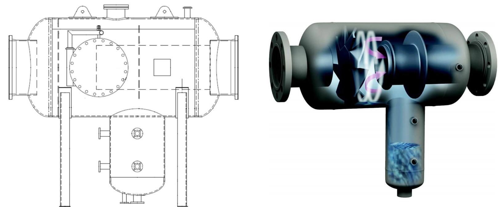
An example of using both knock-out drums and centrifugal separators can be found in petrochemical applications related to manufacturing of plastic resins such as styrene, polystyrene and polyethylene. The specifications typically refer to the first stage as either a knock-out drum or “pre-condenser” to prevent carry-over of entrained liquid and solids into vacuum systems. Centrifugal separators are installed as a second stage to maximize separation of process chemicals so they can be recycled, reducing both waste treatment and chemical make-up. This is a typical design we supply for such an application:

The gas flow enters the separator from the left and it is directed at the center of a fan blade-like structure. The center of the blade (directly opposite of the inlet nozzle) is solid, causing liquid and particles to impinge and coalesce – gravity takes over from there and it collects within the sump. Finer entrained droplets and particles are propelled through the angled “blades”, creating sufficient centrifugal force to propel them to the circumference of the vessel and away from the outlet nozzle on the other side of the blades. Liquid and particles are prevented from becoming re-entrained into the gas steam from a structure within the separator referred to as a vortex containment plate. Its purpose is to cut-off the swirl of entrained droplets from reaching the center of the vessel where the outlet nozzle is located and to prevent carry-out of entrained gas into the sump area.
We can enhance the reduction in velocity by oversizing the vessel body and drain sump to maintain efficiency during upset conditions. An optional inspection port is sometimes desirable for inspection purposes and we can customize the design with any number of additional nozzles.
Let us put our decades of experience to work for you and your next knockout drum or gas/liquid separation application; we often confirm sizing, pricing and lead time within 24 hours and you can call our office and reach an application knowledgeable person to discuss your requirements in detail.
Related Products: TS Gas/Liquid Separators, L1S Gas/Liquid Separators


