
SPEED
EASY NAVIGATION
QUICK RESPONSES
DIRECT SHIPMENTS
GLOBAL SUPPORT
EXCELLENCE
QUALITY SUPPLIERS
PROMPT SERVICE
SATISFACTION IS
#1 PRIORITY
ECONOMICS
LOWEST PRICES
FREE FREIGHT
QUICK DELIVERIES
KNOWLEDGE
FACTORY TRAINED
OTJ EXPERIENCE
ENGINEERING SUPPORT
Common Mistakes When Sizing Centrifugal Separators
Nine errors that cause liquid carryover
Submit your process data using our Inquiry Form or call 908.362.9981 — we reply the same business day.

Centrifugal gas-liquid separators are straightforward pieces of equipment. The mistakes that cause carryover almost always happen during sizing, not because the vortex “stopped working.” Most of those mistakes come from treating separator size as a pipe size, using the wrong design point, or ignoring how much liquid the vessel actually has to hold.
The comments below are based on the same Wright-Austin test basis we use for every quotation: physical testing with wet air at atmospheric pressure and 60°F, then conversion of other gases, temperatures and pressures back to that equivalent. The published result is 99% removal of entrained droplets and particles larger than 10 microns. That efficiency is not the part that usually fails. Capacity and geometry are.
Calling the pipeline size the separator size
A “4-inch separator” is not automatically a vessel with 4-inch flanges. Separator size is an indirect reference to the body diameter and length required to keep internal velocity within the tested range. The published size is the largest inlet ID that can be attached to that body.
It is common, and often correct, to weld 3-inch nozzles onto a 4-inch or larger body. That is not overkill. It is how you satisfy liquid load or pressure drop without restricting the existing pipeline. The opposite is the problem: selecting a 2½-inch body because the calculator returned 2.29 inches, then installing it in a 3-inch line. There is usually an engineering reason that line is 3 inches.
Reducing into a smaller inlet restricts the pipeline and adds pressure drop that was never in the original piping design. Discharging that smaller nozzle back into a larger line then slows the gas. Fine mist that is below the separator’s 10-micron rating can coalesce in that slower section and appear as carryover, even though the separator is doing what it was designed to do. If the body itself is undersized, droplets larger than 10 microns leave with the gas.
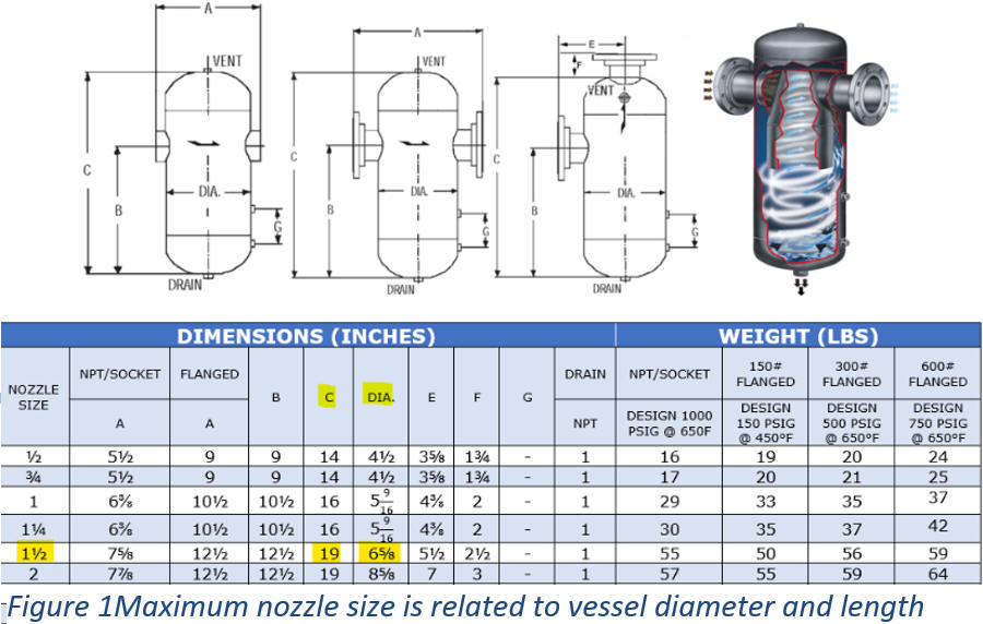
Figure 1. Maximum nozzle size is related to vessel diameter and length
Sizing at “normal” pressure and temperature
The four inputs that set body diameter are gas molecular weight, maximum design temperature, minimum design pressure and volumetric flow. Do not substitute average operating pressure or a mid-range temperature because those numbers are more likely.
Gas density falls as pressure falls and as temperature rises. A separator that is adequate at 125 PSIG and 80°F can be undersized at 40 PSIG and 250°F even if the mass flow did not change. Use the lowest continuous operating pressure and the highest (design) temperature. Upset conditions that last only a few seconds are then only a liquid-load question and not reducing separation efficiency.
Sizing for gas flow and ignoring liquid load
The standard in-line L style separator has a maximum liquid separation capacity equivalent to about 5% of its maximum rated mass flow. Add a sump (LS) and that separation capacity increases to 20%. Vertical up-flow limits the maximum separation capacity to 10–20% depending upon model. The T style is 40% and will take slugs. Elongate that body about 25% and it becomes a TS with a 60% separation capacity. The receiver (R) style adds a second vortex and is rated to 90%.
A separator body that is large enough for the vapor can still pass liquid if that style’s liquid-capacity percentage is below the actual load. Frame the liquid load as a percentage of design flow first, then decide whether using a larger size separator body is less expensive than using a smaller, more complex design. Capacities by style are listed on Separators Grouped by Liquid Separation Capacity and Types of Centrifugal Vortex Separators.
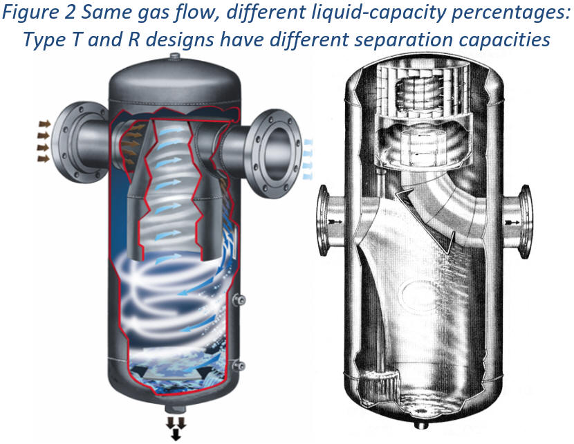
Figure 2. Same gas flow, different liquid-capacity percentages: Type T and R designs have different separation capacities
Assuming efficiency falls off at low flow
Centrifugal inertia is lower when velocity is lower. That statement is true and it is also incomplete. Gravity does not change, and residence time increases as the droplets move slower. The trajectory of a droplet that would have been swept toward the separator outlet at high flow is downward at low flow. That is why centrifugal separators hold 99% efficiency with what is effectively an infinite turndown.
The failure mode is the other direction. Undersize the body and velocity around the outlet pipe stays high enough that droplets never reach the wall or the vortex containment plate. Coalescence and drainage never get a chance to finish. You cannot usefully undersize a centrifugal separator. You can oversize one. The physics is covered in Understanding Centrifugal Inertia and Separation Efficiency.
Treating a knock-out drum and a centrifugal separator as the same calculation
A knock-out drum is a large vessel that relies on expansion, low velocity and gravity. It has no requirement for an impingement plate or a vortex containment plate. The diameter of a knock-out drum is related to residence time, not from a tested centrifugal velocity limitation.
If you apply knock-out drum rules to a centrifugal separator design, you will either buy a vessel that is much larger than necessary or you will expect slug capacity that the internals were never designed to provide. Conversely, if you apply centrifugal sizing to a bare drum, you will overstate what that drum can do with fine droplets. They are related pieces of equipment. They are not interchangeable formulas. See Knock-Out Drums vs Centrifugal Gas-Liquid Separators.
Expecting the separator to remove vapor
Centrifugal force and gravity act on mass. A droplet or particle larger than 10 microns is heavier than the gas and leaves the stream. Water that has already vaporized is part of the gas. No change in body diameter fixes that. If the problem is dew point, then the process will require a cooler, a coalescing stage or a dryer — not a larger size separator body.
The same distinction applies when someone specifies a coalescing or polishing stage “to be safe.” A coalescing stage ahead of the vortex results in >5 micron separation; a polishing cartridge after the vortex is for >0.3 micron separation. It is not a substitute for sizing the centrifugal stage correctly, and it adds internals that eventually have to be cleaned or replaced. The single-stage designs have no serviceable parts; they require zero maintenance. Fine-mist designs are described in Coalescer Gas-Liquid Separator Designs.
Ignoring allowable pressure drop
The sizing calculation produces a differential pressure for the selected body. On a 150 PSIG steam line a few tenths of a PSI is rarely the deciding factor. On a low-pressure blower, a vacuum system or a fuel-gas line to a burner, it can be a critical design criterion.
If the calculated drop is too high for your application, increase the body size. There is no way to reduce the differential pressure after the fact by “opening a drain” or modifying the internal geometry because those internals exist to separate entrained droplets and prevent them from exiting the outlet nozzle. The cost-effective method of satisfying the required maximum differential pressure is to increase the diameter and length of the separator and fabricate it with a nozzle size matching your existing or intended pipeline size.
Sizing the vessel and forgetting the drain
Separated liquid that cannot leave the vessel is re-entrained liquid. A float drain trap sized for the continuous condensate load will flood when a slug arrives if the orifice and body of the trap are not large enough to handle an upset condition or design liquid load. With some separator designs sight-gauge ports exist so you can visually confirm proper drainage. Where liquid level is used to actuate drainage or provide a signal to a PLC, the separator body must have a hold-up capacity.
If the process liquid is dirty, viscous or tends to flash across the trap orifice, the trap becomes the sizing problem even though the separator body is correct. High-solids service may require a special clog-resistant separator body design along with a rotary style valve rather than a conventional ball valve.
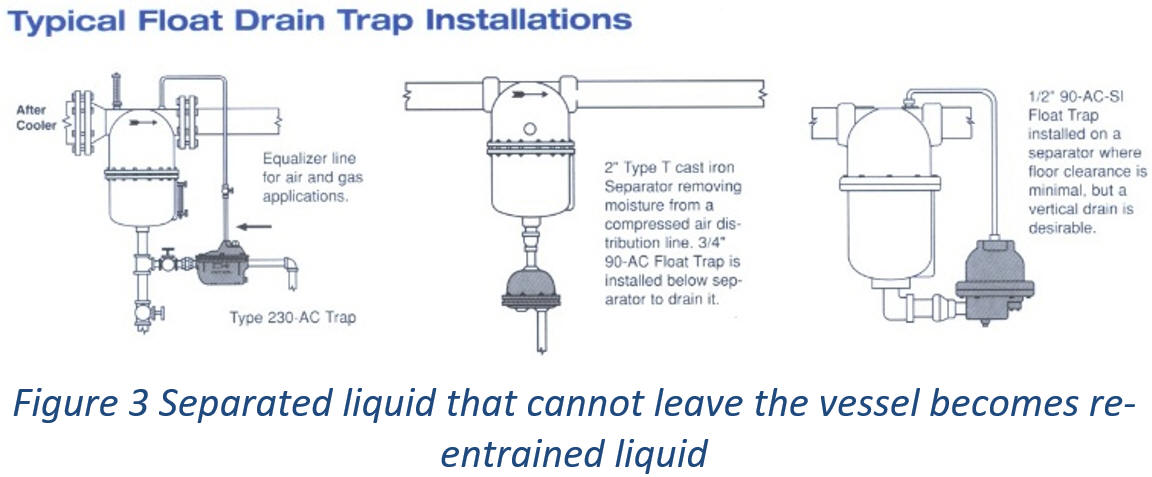
Figure 3. Separated liquid that cannot leave the vessel becomes re-entrained liquid
Using the wrong orientation for the liquid load you actually have
Several separator styles have different liquid separation capacities even when the flow orientation is the same. That matters most when a separator is being added to an existing piping system. If the orientation cannot change, use a style whose published liquid-capacity percentage covers the load — or increase the body size.
What to send us instead of a guess
The calculators on our websites will provide the minimum separator body size required in just seconds; required inputs are: molecular weight, maximum temperature, minimum pressure and flow rate of your vapor. That resulting size is the starting point and not necessarily the optimal size for your specific application. Consider the expected continuous liquid load, whether slugs are possible, the maximum pressure drop you can accept, the existing pipe size and whether the flow path is horizontal or vertical. In addition, if your flow rate is pulsating (reciprocal compressor) 2x the design flow rate for sizing.
We use those extras to decide the most cost-effective separator model
for your application and is the difference between a separator that matches
the catalog page and one that matches the process.
Use our Inquiry Form or call 908.362.9981 — we reply the same business day.