Horizontal Gas Liquid Centrifugal Separators
Droplet separators 99% efficient for droplets >10 microns
Horizontal style gas liquid separators have inlet and outlet nozzles located on the same plane and are often in-line (180°apart) although the outlet nozzle can be offset 90°to 270° from the inlet nozzle if needed. All of our single stage centrifugal separators are designed to remove droplets and particles greater than 10 microns with 99% efficiency, however their specific internal design affects the rate or capacity of droplets that can be removed. Liquid removal capacity is expressed as a percentage of the separators maximum weight flow capacity, thus we convert the separators volumetric flow to weight flow and then based upon a given separator design we can estimate the liquid removal capacity.
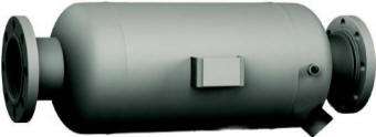
L Style Gas Liquid Separator
| Type: | Horizontal, single stage |
| Maximum entrained liquid removal: | 5% of the maximum weight flow capacity (10% when the nozzles are offset by 90º) |
| Will it handle "slugs" of liquid: | No |
| Maintenance required: | None |
The L style gas liquid separator is the most common and inexpensive horizontal gas
liquid separator design, consisting of a cylindrical pressure vessel having an
inlet and outlet in addition to vent and drain ports. This style
of separator may also be used for vertical down flow orientation.
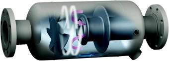
The air, steam or other gas enters the vessel and encounters a
baffle having slots located at right angles to the process flow.
Due to reduction in velocity and inertia, most droplets impinge on the
baffle and coalesce to larger droplets.
The gas flow though the
baffle creates a vortex induced centrifugal force, propelling entrained
droplets larger than 10 microns away from the vessel outlet and towards
its walls. All of the coalesced liquid exits through the drain port.
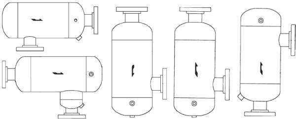
The L style gas/liquid separator can be configured with a variety of inlet and outlet nozzle orientations:
LS Style Gas Liquid Separator
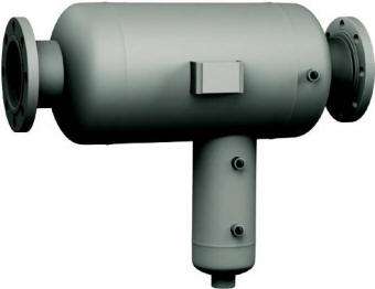
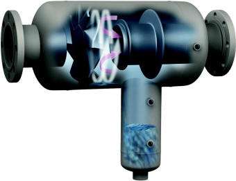
| Type: | Horizontal, single stage |
| Maximum entrained liquid removal: | 20% of the maximum weight flow capacity |
| Will it handle "slugs" of liquid: | Yes |
| Maintenance required: | None |
The LS style is the same as the L style with the addition of a sump and this enables both a higher liquid removal capacity and ability to handle slugs of liquid. "Slugs" refer to liquid that travels through the pipeline in irregular volumes, typical of low areas of piping where liquid accumulates until nearly blocking the pipeline, then the gas propels this liquid downstream.
Applications which require a "hold-up volume" of liquid in support of ensuring proper pump head or chemical reactions also benefit from the addition of a sump.
T style Gas Liquid Separator
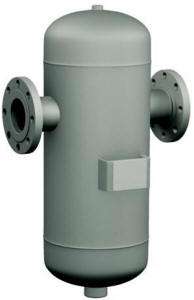
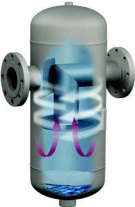
| Type: | Horizontal, single stage |
| Maximum entrained liquid removal: | 40% of the maximum weight flow capacity |
| Will it handle "slugs" of liquid: | Yes |
| Maintenance required: | None |
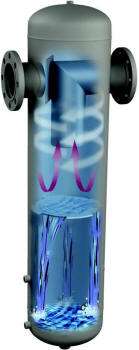
The T style gas liquid separator is the most common design used due to its relative high liquid removal capacity and ability to handle slugs of liquid. Unlike the L and LS styles where the gas flow and associated vortex is horizontal, type T gas liquid separators create a vertically oriented vortex with a indirect flow path. Thus most entrained liquid impinges upon the internal structure of the separator and due to angular momentum only droplets finer than 10 microns can pass though the low velocity section of the vortex.
A vortex containment plate located at the bottom of the vessel prevents re-entrainment of the separated liquid. Liquid level gauge ports and inspection ports are optional. As with all of our single stage separators there are no moving or serviceable components, it is a fully welded pressure vessel never requiring maintenance. Internally it is kept clean by the constant swirling vortex.
Type T separators are a custom fabricated pressure vessel, however we do offer type T gas liquid separators in cast iron. The cast iron versions are typically used for compressed air and steam applications having the advantage of low cost and quick shipment compared to the fabricated versions.
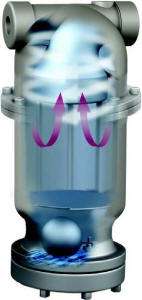
The cast iron type T separators are available with an integral float drain trap called a type ST. Air and steam applications in particular often discharge the separated water to drain and thus benefit from a float drain trap which will automatically drain liquid from the separator without any loss of process gas. While we offer float drain traps in cast iron, steel and 316SS, the type ST separators have this trap included within the separator body to simplify installation.
TS style Gas Liquid Separator
| Type: | Horizontal, single stage |
| Maximum entrained liquid removal: | 60% of the maximum weight flow capacity |
| Will it handle "slugs" of liquid: | Yes |
| Maintenance required: | None |
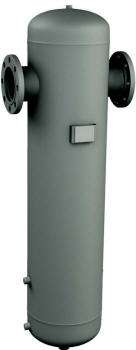
TS style gas liquid separators are a modified version of the T style gas liquid separators described above. The body of a TS separator is elongated, thus the volume between the vortex containment plate and drain port is significantly increased. This design is used for heavier liquid loading and to provide a hold-up volume for applications which use a pump to transfer the separated liquid from the vessel.
R style Gas Liquid Separator
| Type: | Horizontal, single stage |
| Maximum entrained liquid removal: | 90% of the maximum weight flow capacity |
| Will it handle "slugs" of liquid: | Yes |
| Maintenance required: | None |
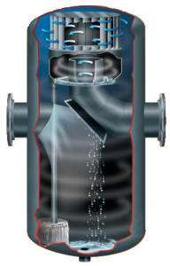
The R style separator is designed to remove the maximum volume of entrained droplets for a given body size. When you have a high volume of liquid to remove you can oversize type T and TS separators or elect to use a type R to minimize the physical size of the separator body. The internal complexity of a type R gas liquid separator enables it to remove entrained liquid equivalent to 90% of its maximum weight flow capacity. Due to cost, it is common to oversize a type T or TS separator, therefore type R separators are frequently used when there is limited space for installation.
Although still considered a single stage vortex separator there are actually two vortexes created in type R separators. The first vortex occurs within the main body of the vessel and only the finest droplets travel to the top of the vessel where the internal baffle is located. This internal baffle has angled fins resulting in a second vortex ensuring droplets larger than 10 microns cannot travel into the low velocity area where the exit nozzle piping is located.
The separated liquid from the second stage is piped to the bottom of the vessel where the other liquid accumulates.
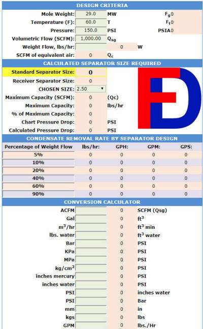
When you use our sizing calculator (screen capture below) we list the maximum liquid removal capacity in both mass and volumetric flow rates. When combined with the chosen size variable you can easily determine which size separators by model (percentage of weight flow removal) would satisfy your requirements. Please refer to our article about How to Size a Centrifugal Separator for detailed instructions of how to use our sizing tool. (or just send us an inquiry!)
