Efficiency of Centrifugal Vortex Separators

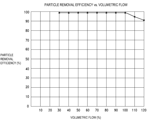
Centrifugal or “vortex” separators remove particulate and entrained droplets larger than 10 microns from air, steam or other gaseous applications with 99% efficiency.
Our article: “Design
and Capabilities of Gas/Liquid Separators” describes the general
centrifugal separator design and physics which contribute to the separation
process. The following provides a brief description of the standard
centrifugal separator vessel configurations available for your
application.
The L Series
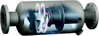
 In its simplest form, the “L” Series separator
consists of a cylindrical body horizontally in-line with the pipeline to
which it is installed. Gas flows into the separator body encountering a
vaned impingement plate, forcing the gas to pass through the circumference of
the vessel at an angle thus creating a vortex on the other side.
Droplets either directly impinge onto this vane or are propelled to the
circumference where only the finest navigate through the angled vane
openings. The droplets and particles accumulate and coalesce at
the bottom of the centrifugal separator, to a common drain port.
Due to angular momentum, the fine droplets that passed through the vane
are unable to “navigate” towards the low velocity center of the vessel
where the outlet nozzle pipe is located and they subsequently impinge
onto the inner circumference of the vessel body or the vortex containment plate mounted to the
internal exit nozzle pipe.
The “L” Series can separate a liquid
load equivalent to 5% of the maximum rated mass flow rate for a given size
vessel.
A centrifugal separators “size” is not necessarily the
same as the “size” as the inlet and outlet connections; it often is, but
doesn’t have to be. The mathematical calculations used for sizing
a centrifugal separator relate to the vessel ID, vessel length and the
total area of internal vane or separator element within. If the
liquid load is high, options include using a slightly more complex
configuration (minimizing the vessel size) or using a larger vessel and
attaching smaller size connections to match the existing pipeline.
What the separator "size" more accurately refers to is the maximum inlet
size for that separator body diameter and length.
The simplest modification to a Type L is the addition of a sump, which we refer to as an “LS”. The sump increases the liquid removal capacity to the equivalent of 20% of its maximum rated mass flow. The sump simply provides extra space for liquid to flow into without chance of being re-entrained.
The “L” Series can be further customized to have different size inlet/outlet nozzles, have a horizontal inlet and vertical outlet or vice-versa and they all have that same 20% liquid maximum removal capacity with one exception: it is reduced to 10% of the maximum rated flow capacity when the flow path is vertically upwards.
If the liquid load is greater
than 20% or if occasional “slugs” of liquid need to be removed it requires a
slightly more complex design.
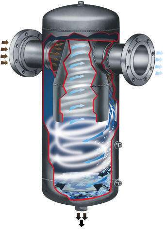
The “T” style operates on the same
principles with the vessel body oriented 90° to the horizontal pipeline to
which it is installed. This design utilizes an angled deflector plate
to create the centrifugal vortex and due to the location of the outlet
nozzle pipe, gravity assists with the removal rate. The lower portion
of the vessel is also a built-in sump with a vortex containment plate
preventing re-entrainment of the separated liquid. Only droplets finer
than 10 microns can be drawn out through the low velocity area of the vortex
where the outlet nozzle pipe is located.
 The
Type “T” gas/liquid separator has a separation capacity equivalent to 40% of its maximum
mass flow capacity.
If we elongate the body of a Type “T” by
approximately 25% it becomes what we refer to as a Type “TS” and is now
capable of a liquid separation rate equivalent to 60% of its maximum
mass
flow capacity.
Applications having a very high liquid load, or
more commonly an upset condition resulting in a large “slug” of liquid
may require the “Receiver” style centrifugal separator, simply referred
to as a Type “R”.
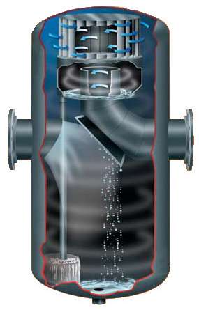
The internal complexity of the Type R is slightly more
than the Type T due to the addition of a secondary vortex. Instead
of the gas exiting through the low velocity (center) of the initial
centrifugal vortex, the gas travels to the topside of the vessel and
must pass through angled vanes; the outlet nozzle pipe is located in the
low velocity (center) of this secondary vortex. The Type “R” centrifugal
separator has a liquid separation capacity equivalent to 90% of its maximum
mass flow capacity.

All of the aforementioned centrifugal separators
maintain 99% efficiency for removal of droplets and particulate greater
than 10 microns without any moving or serviceable components. They
are considered self-cleaning due to the constant centrifugal vortex
forces and require zero maintenance.
To accommodate applications requiring
separation of
droplets >5 microns an additional coalescing stage is added prior to
the centrifugal vortex stage.
We can separate even finer
droplets, as fine as 0.3 microns with 99% efficiency, by installing a “polishing stage” after the centrifugal vortex.
Specially designed borosilicate microglass filter cartridges are used to
channel these fine droplets to a coalescing drain point.
The
addition of a coalescing or polishing stage increases the vessel
complexity periodically the internal elements require cleaning or
replacement.
How to you select the “best” centrifugal
separator design for your application?
We have created
the only known publically available,
Internet based centrifugal separator sizing tool and it
is designed to
help you compare your options.
After inputting just (4) design
criteria the “separator size” is calculated; we show two different
values, one for the Type “R” (receiver style) and the highlighted size
applicable to all of the other “standard” separator designs.
To
simplify the selection process, “size” is referring to the maximum inlet
connection ID as relates to the vessel diameter and length. This
is a nuanced delineation that I will explain further with our example.
Our example application therefore would require a
2.5” centrifugal separator or a 3” receiver style separator as both 2.5”
and 3” are standard pipeline sizes.
Inputting “3” for the size
calculates the maximum capacity (volumetric and mass flow), the
differential pressure and chart of maximum liquid removal rates.
Additional factors that affect sizing include the liquid load to be
removed and differential pressure.
If the calculated
differential pressure is too high for your application, increase the
size of the separator until it meets your requirement.
Likewise
use the liquid removal capacity chart to determine which separator
design is required; this is where things can get interesting.
If
keeping the vessel size to a minimum is critical, moving up the chart to
the 90% (receiver style) might make sense, however if you have “extra
space” it might be less expensive to use a larger size “L” or “T” style
because they are not as complex to manufacture.
Size
Matters!
You cannot “oversize” a separator; the 99%
efficiency will be retained, however you can certainly “undersize” a
separator. Technically what happens when a centrifugal separator
is undersized is that the velocity around the outlet nozzle pipe is high
enough to prevent the droplets from impinging to the vessel walls where
coalescing and gravity take-over. So we can easily “oversize” a
centrifugal separator and attach to it smaller inlet and outlet
connections to match your piping to handle your liquid load or
differential pressure requirements. Remember the “minimum size” of
2.29” in our example is also related to the minimal internal diameter
and length of the vessel, so anything larger increases the separation
efficiency.
It is not recommended to install a separator having
an inlet size smaller than the pipeline it will be attached to, even if
the design criteria indicates a smaller size would be sufficient.
The thought behind this is that there is likely an engineering reason
for the existing pipeline size and it’s usually not a good idea to
unnecessarily restrict it.
The sizing tool is available to
assist you with a better understanding of your options. We typically
prompt you for the applicable design criteria and an overview of your
application to provide a proposal, however you can use this tool to
approximate the physical dimensions of the required separator and to have a better feel for the
performance vs. pressure drop as compared to vane and mesh pad style
separators which typically are physically larger (expensive) and have
higher pressure drops (not to mention require periodic maintenance and
lose efficiency at low flow rate conditions).


