How to Size a Moisture Separator
Charts, formulas and web-based calculators for separator sizing
Our article “Understanding
Sizing Factors for Centrifugal Separators” described what a
centrifugal separator is, the key design criteria required for proper sizing and
how to use our web-based sizing tools. In this article we explain the
sizing charts and formulas of which the web-based calculators are based upon.
The two articles combined enable you to both properly size a centrifugal vortex
separator and compare performance criteria of liquid removal and pressure drop
amongst several separator designs.
We use two charts for sizing separators, one for steam and another for all
other gases. We will review sizing for steam applications first because it
is more simplistic.
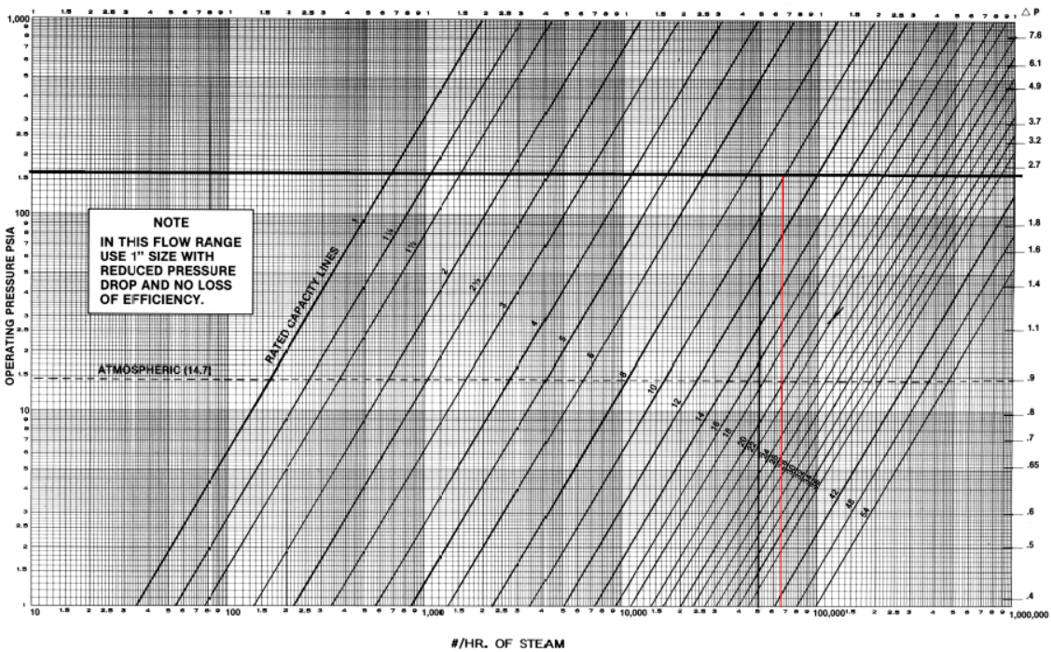
The sizing charts have a X, Y and secondary Y axis. The X axis lists
the mass flow rate of steam or the volumetric flow rate for air depending upon
the chart. The Y axis lists absolute pressure (PSIa) and the secondary Y
axis the corresponding differential pressure (∆P). The diagonal lines
across the chart are the performance curves for standard separator sizes.

The first step is to draw a horizontal line from the design (maximum) PSIa across to the differential pressure (secondary Y axis).
Next draw a vertical line from your design (maximum) flow rate of steam in lbs/hr units. The separator size required is indicated by the line to the right of where your two lines intersect.
To calculate the corresponding differential pressure for your application, use the following formula:

Since centrifugal vortex separators have an infinite turndown ratio they
maintain their separation efficiency at lower pressures associated with start-up
and shut-down.
Moisture Separator Sizing for Air and Other Gasses
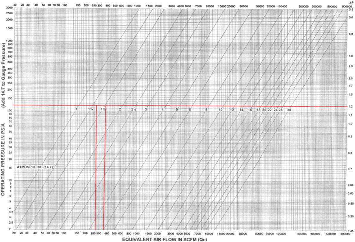
The procedure for sizing air and other gas applications is the same with
respect to drawing horizontal and vertical lines, the difference is that the
volumetric air flow needed to use the chart is the “Equivalent Air Flow in SCFM
(Qc)”.
Qsg is the rate of flow in CFM


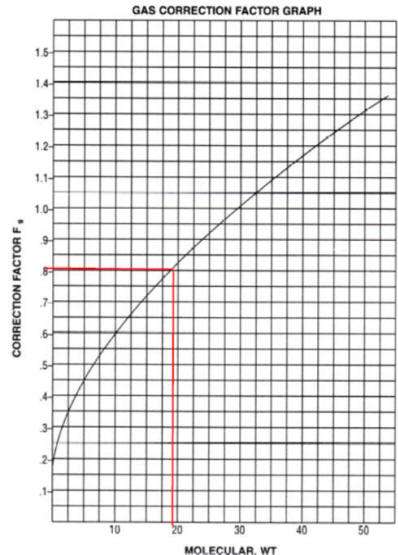
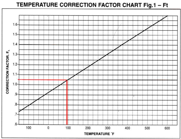
We have tables and graphs for Fg and Ft and from those we have derived formulas. There are several ways to calculate Qsg, the easiest is probably
 .
If your gas is a composition of several different gasses you will need to
calculate the equivalent MW using the percentage of each gas in your
composition.
.
If your gas is a composition of several different gasses you will need to
calculate the equivalent MW using the percentage of each gas in your
composition.The MW for our calculations is 19 (75% of 16 + 25% of 28). And thus Qsq=
 =
331.58 CFM.
=
331.58 CFM.We have a table specifying Fg for Natural Gas is 0.788 and if you use the graph it would seem to be 0.8; when we have a value in table format we will use that instead of interpolating from a graph; our calculators use a formula.
Next is Ft, and we again have both a table and graph to consult; the table specifies Ft = 1.034 and the graph Ft = 1.05, so we’ll go with the table. Now we can calculate Qc = 331.58 x 0.788 x 1.034 = 270.16 SCFM.
The intersecting lines indicate a 1½” separator is required and its maximum flow rate is 350 SCFM with a rated ∆P of 1.2 PSI. Thus the actual differential pressure is calculated as 0.715 ∆P.

Now that you know the size of the separator you will need to determine which model suits your application the best.
Additional criteria to consider include the volume of condensate to remove, your piping size and orientation, droplet size to remove and physical space available to install the separator. This aspect of separator selection is described in our article “Efficiency of Centrifugal Vortex Separators”.
Our web-based sizing tool automatically calculates Qc and both rated and actual ∆P. In addition, it provides the liquid removal rate for all size separator designs. You can also toggle the size to adjust the liquid removal rate and actual ∆P to quickly determine the separator size and model for your application. If you have several applications or want to quickly see the effect of changing a variable such as pressure, the online sizing tool is invaluable.
Although we have provided you with the fundamental information and tools to properly size a centrifugal separator for your application, we are here to assist you! Please contact us by phone, email or web-based inquiry form so we can put our experience to work for you!


