• Speed

    SPEED
    EASY NAVIGATION
    QUICK RESPONSES
    DIRECT SHIPMENTS
    GLOBAL SUPPORT

  • Excellence

    EXCELLENCE
    QUALITY SUPPLIERS
    PROMPT SERVICE
    SATISFACTION IS
    #1 PRIORITY

  • Economy

    ECONOMICS
    LOWEST PRICES
    FREE FREIGHT
    QUICK DELIVERIES

  • Knowledge

    KNOWLEDGE
    FACTORY TRAINED
    OTJ EXPERIENCE
    ENGINEERING SUPPORT

TYPE T GAS-LIQUID SEPARATORS

Droplet separators 99% efficient for droplets >10 microns

T separator specifications


Fully welded pressure vessel fabricated to ASME Code Section VIII Division 1 with stamp, has no serviceable/moving components, requires zero maintenance.

Separates entrained droplets and particles larger than 10 microns in diameter with 99% efficiency. Maximum separation rate is equivalent to 40% of its maximum rated mass flow capacity and will separate slugs of liquid.

The “G” ports exist to visualize proper drainage with a sight gauge and not for a liquid hold-up level as if the liquid level reaches the lower “G” port it is not draining from the separator quick enough. Utilize the type L1S or TS gas/liquid separator when a liquid hold-up level is required.

The separator size required is based upon the required vessel length and diameter and not necessarily the corresponding inlet and outlet pipeline size; thus, we size the nozzle to match the pipeline for which it is installed into.

Typically manufactured from pipe, they can be fabricated from rolled plate; standard materials include carbon steel, 304L SS and 316L SS although they can be fabricated in other alloys when required.  We also offer 1½ through 4” sizes in cast iron, typically less costly then fabricated separators and a lead time from stock to 2 weeks. Customizations include support legs, additional ports and non-flanged connections.
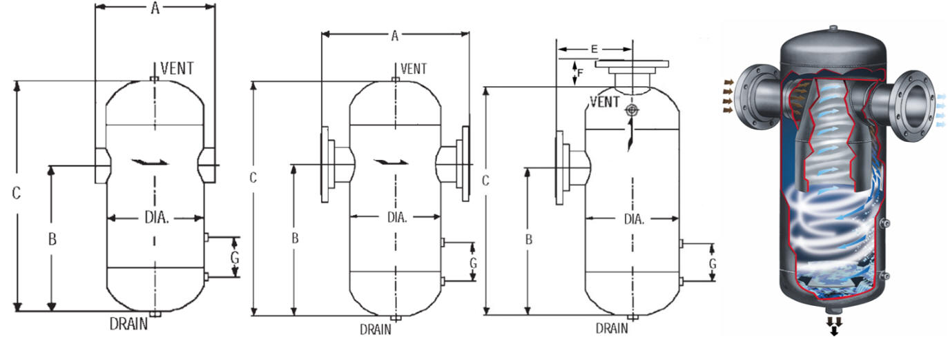
 

T gas-liquid separator drawing

T gas-liquid separator dimensions


CAST IRON TYPE T AND ST GAS-LIQUID SEPARATORS

Cast iron type T and ST (containing an internal float drain trap) are inexpensive alternatives for gas/liquid separation when an ASME Code Stamp is not required and when cast iron material is compatible with the media and pressure/temperature conditions.

The ST separators (with internal drain trap) have flanged bottoms to enable periodic replacement of the internal float valve assembly).  Since most air and steam applications for cast iron type T separators require an external float drain trap, the type ST separator provides a slightly more economical design by simplifying installation. The standard drain orifice is 3/32” supporting a condensate drainage rate of:

Condensate Drainage Capacity for 3/32” orifice in lbs/hr based upon differential pressure:

ST separator drainage rate


Both T and ST separators separates entrained droplets and particles larger than 10 microns in diameter with 99% efficiency

Maximum separation rate is equivalent to 40% of its maximum rated mass flow capacity and will separate slugs of liquid.

The “C” ports exist to visualize proper drainage with a sight gauge and not for a liquid hold-up level as if the liquid level reaches the lower “C” port it is not draining from the separator quick enough. Utilize the type L1S or TS gas/liquid separator when a liquid hold-up level is required.

Unlike fabricated gas/liquid separators, cast iron separators cannot be customized with reduced nozzle sizes, additional ports or having modified dimensions; they are intended for air and steam applications. Lead times range from stock to 2-3 weeks for assembly when components are in-stock; if cast components are not in-stock the lead time is foundry based (months).


Cast T gas-liquid separator drawing

Cast T gas-liquid separator dimensions