 Download R-Series Specs
 The
R-Series centrifugal separators double as high-performance knockout
drums, designed to remove liquid from gas streams in oil, gas, and
industrial systems. With proven century-old technology, these units
offer low maintenance and reliable separation. Explore specs below
or
Compare knockout drums vs. centrifugal separators.
Receiver
gas/liquid separators are specifically designed to separate heavy liquid loads
and large liquid “slugs”. Another way of describing their design is that
when the liquid load is the driving factor for sizing the physical size of the
separator, the receiver style separators can be used to minimize the physical
size of the separator. In steam systems receiver style separators are also
used as a flash tank or demister ahead of steam turbines.
Knockout Drum Applications
-
Oil & gas pipelines
-
Compressor protection
-
Flare systems
Fully welded pressure vessel fabricated to ASME Code Section VIII Division
1 with stamp.
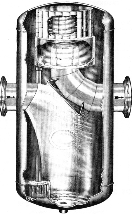
Receiver gas/liquid separators separate entrained droplets and particles
larger than 10 microns with 99% efficiency and have no serviceable or moving
components, thus require zero maintenance.
Their liquid separation capacity is equivalent to 90% of their mass flow
rate capacity, the highest of all separator designs. While the other
centrifugal separator designs immediately cause the process gas to enter a
centrifugal vortex, the receiver style ensures significant droplet coalescence
by diverting the process gas to a deflection surface. Most of the
entrained liquid never reaches the top section of the separator body. To
exit the vessel the gas must travel upwards and enter a centrifugal vortex
chamber via angled plates where the center of the exit nozzle extension tube is
within the low-pressure center of the vortex. Centripetal force and
inertia combined with gravity ensure that droplets larger than 10 microns
coalesce to a common drain.
The physical size of the separator (its diameter and length) is determined
by the maximum volume of gas passing through the separator and not necessarily
corresponding inlet and outlet pipeline “size”. Gas/liquid separator
“size” is an indirect reference to the diameter and length of the separator body
with the inlet and outlet nozzle ID being the largest which can be attached to
the required circumference of the separator body, thus a 10” size separator may
have 10” or smaller inlet/outlet nozzles to match pipeline it will be installed
into.
Typically manufactured from pipe, they can be fabricated from rolled
plate; standard materials include carbon steel, 304L SS and 316L SS although
they can be fabricated in other alloys when required. Customizations include
support legs, additional ports and non-flanged connections

Related Products:
TS Gas/Liquid Separators,
L1S Gas/Liquid Separators
 The
R-Series centrifugal separators double as high-performance knockout
drums, designed to remove liquid from gas streams in oil, gas, and
industrial systems. With proven century-old technology, these units
offer low maintenance and reliable separation. Explore specs below
or
Compare knockout drums vs. centrifugal separators.


