Natural Gas Cyclone Separators
Natural gas separator design
Call us at 908.362.9981 to speak with a sales engineer

The natural gas extraction process results in significant entrained
liquid and solids that our cyclone separators are designed to remove
right at the wellhead. These pipeline damaging particulate
also affect the efficiency of heat transfer and overall energy
consumption. Natural gas cyclone separators will remove 99% of
entrained droplets and particles larger than 10 microns in size.
Our cyclonic separators are inherently reliable due to their fully
welded design, having no internal components that require servicing or
cleaning.
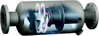
The body of our natural gas cyclone separators is
matched to the element size within to ensure adequate area to remove the
particulate with a negligible differential pressure. Our design has
no internal mesh elements or fine channels which require cleaning.
As the natural gas enters the separation vessel the entrained
particles experience a reduced velocity due to the vessel having
significantly more volume than the inlet pipeline, resulting in the
larger contaminates falling to the bottom of the vessel.
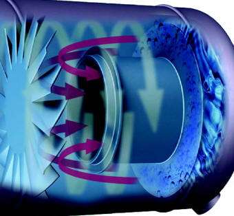
The
internal geometry within the separator generates centrifugal force,
significant enough to propel high mass particulate to the vessel walls,
where they coalesce and fall to the bottom due to gravity. The
less dense gas containing droplets finer than 10 microns exit via
a tube extending into the center of the centrifugal vortex and directly
out of the vessel according to the desired flow path of your piping.

A baffle referred to as the vortex containment plate (VCP) is located near the drain
port to prevent agitation and reentrainment of separated liquid and particles.The constant centrifugal vortex
results in a scrubbing-like effect so it does not require cleaning.
Our 99% efficiency is maintained with an infinite turndown ratio,
meaning that we maintain 99% efficiency during start-ups, shut-downs and
system upsets related to lower flow rates.
The liquid handling
capacity is typically expressed as a percentage of the overall weight
flow and we have designs for 5% to 90% liquid loads. Higher liquid
loads require separators with a more complex internal geometry as well
as an increased internal surface area.


