Exhaust Head Design
Applications for Exhaust heads
Call us at 908.362.9981 to speak with a sales engineer
 This
article is the third in a series of articles describing gas/liquid
separation via centrifugal force; it describes a specialized type of
vortex separator referred to as an exhaust head and complements our
articles
Gas/Liquid Separator Designs and
Coalescer Gas/Liquid Separator Designs.
Centrifugal
Separation Explained
Vortex separators, commonly referred to
as centrifugal separators, rely on centripetal force to overcome the
inertia associated with droplets and particles larger than 10 microns
such that their trajectory is curved away from the vortex and outlet
nozzle and instead impinge upon the internal structure to coalesce to a
common drain.
Advantages of centrifugal separation
include:
1. high efficiency (99%) removal of entrained
droplets >10 microns
2. reduced vessel size compared to mesh pad and
vane styled separators; directly corresponds to reduced cost
3.
simplicity of design has no serviceable or wearing components; there are
no maintenance requirements.
Exhaust Heads Differ from
In-Line Separators
Whereas an in-line separator has both an
inlet and outlet pipeline connection, exhaust heads only have a pipeline
connection to its inlet as the outlet is open to atmosphere.
This
is a limiting factor relegating exhaust heads to certain types of
applications involving venting of non-hazardous gasses and liquids.
Current exhaust head design is credited to
Mr. Arthur J Filkins and his 1925 patent for “Exhaust head for exhaust
steam pipes”. The application he invented it for, removing entrained
liquid (water droplets, trace lubricants and boiler treatment chemicals)
from steam vent pipes remains the most common application for exhaust
heads.
An exhaust head reduces the carry-out of liquids and
associated contamination, which can be as innocuous as reducing rooftop
icing in cold environments to reclamation of chemistry that otherwise
would be contaminating the surrounding environment. The reduced exit
velocity inherent with centrifugal separator design also corresponds
with reduced projection into the surrounding environment.
Unintended Benefit
Due to the design of centrifugal
or vortex style exhaust heads, the noise associated with high velocity
venting is somewhat reduced. This sometimes leads to confusion between
an exhaust head and vent silencer.
A vent silencer is designed to
reduce the noise associated with venting a pipe to atmosphere due to the
sudden expansion of the gas being vented. This is accomplished by using
sound absorbing materials and creating a reactive section to reduce low
frequency noise. Liquid separation due to the internal geometry of vent
silencers may be considered an unintended benefit.
Thus, exhaust
heads are designed to remove entrained liquid with any noise reduction a
non-engineered “benefit” and vent silencers are designed to reduce
noise; any liquid separation is a non-engineered “benefit”.
To
engineer or maximize both liquid removal and noise reduction would
require installation of an in-line separator prior to a vent silencer.
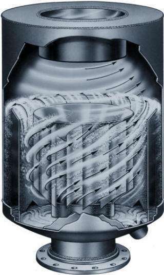
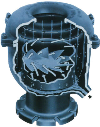
Exhaust Head Design
Since all of the other
vortex separator models are designed and manufactured in accordance to
ASME Division I, Section VIII and stamped, exhaust heads are
manufactured in-kind however since they are not pressure vessels, they
cannot be code stamped.
Atmospheric pressure is the design
pressure standard for exhaust heads and they are sized to have a ≤ ∆ 0.9
PSI pressure drop. This aspect often leads to confusion of piping design
specifications associated with a given site, as the last piece of
equipment cannot be code stamped and its “maximum pressure” is described
as only 14.7 PSIG even though it has a fully welded design and often
with 150 lb. class flanged connection. The internal welding of the
separation impeller, vortex containment plate, inlet and drain
connections are all in accordance to ASME code simply because that is
the manufacturers standard.
 Exhaust
Head Applications
Reduced opacity and projection of vented
steam accomplished by removing droplets larger than 10 microns with 99%
efficiency and reduced exit turbulence. A consequential benefit includes
reduced noise attributed to the both reduced turbulence and an indirect
path to atmosphere. The rooftop and surrounding environment are subject
to less liquid carry-out and the removed condensate may be reclaimed to
reduce chemical and water make-up.
Steam exhaust heads are often
constructed of carbon steel and have a 304SS internal separation
impeller. The inlet connection can be threaded, flanged or butt-weld to
match the corresponding vent pipe. If the environment is corrosive, such
as an off-shore natural gas or oil rig, they can be supplied in 304SS,
316SS or other alloys. For pipeline sizes ≤ 10” we offer cast iron
designs for a significantly reduced cost and lead time compared to
custom fabricated designs.
Air exhaust is another somewhat common
application for exhaust heads. Sometimes there are processes involving
mixing vessels or machining centers which are too numerous to vent
through the rooftop and perhaps cost prohibitive to tie into a
centralized exhaust system.
Whether it is lubricants, steam or
wet air in some localized and contained process, an exhaust head
provides a relatively inexpensive method for removing those entrained
droplets and protecting the surrounding personnel/environment. Such
applications are still typically accommodated by cast iron or fabricated
steel designs, although some food, beverage and biopharmaceutical
applications may require stainless steel construction.
Lifespan of an Exhaust Head
Since exhaust heads are fully
welded or cast and have no moving or otherwise serviceable components,
they have no maintenance requirements and an indeterminate lifespan.
Usually exhaust heads are replaced when the process conditions change,
relegating the existing exhaust head less efficient. If an exhaust head
is unable to drain, the condensate will contribute to oxidation which
can eventually compromise the integrity of the body.
They are
designed such that water from the external environment flows directly to
the exhaust head drain and does not bypass the exhaust head, so even
when not in operation, standing liquid should not be a problem as long
as the drain port remains open and unblocked. When an application is
intermittent and there is concern of birds or other animals nesting
within the exhaust head, we can attach a screen across the outlet to
discourage that from happening.
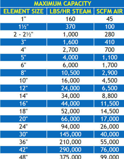
 Sizing an Exhaust Head
As with their inline versions, the physical body of an exhaust head
required for an application (its internal diameter, surface area and
volume) is dictated primarily by the volume of steam or air to separate
and NOT the inlet pipe size. When we refer to a given “size” separator,
we are referring to the maximum corresponding inlet nozzle size that can
be used, but there is no “minimum” size. For example, an application
having a 4” size vent pipe might require a 6” size separator, to which
we can attach a 4” connection to match the intended vent pipe size.
Likewise, a 4” vent pipe might only require a 3” size separator from a
performance perspective, however it would require using a 4” size
separator to match the intended pipeline size.
Our expertise lies
with understanding the applicable design criteria for a given
application and providing detailed proposals for the most cost-effective
design.
Let us know
how
we can assist you with your separation application!


